Wednesday, July 10, 2013

Recovering lost partition table on a VMFS

It’s just a procedure tried and worked
So I can’t assure 100% guarantee and it’s just an experimental procedure to recover latest vmfs 5.0.
Steps I tried to experiment the same.
  • Created two 4GB iSCSI LUN and presented to ESXi 5.0.
    • From vSphere Client create a datastore from first 4 GB LUN.
    • Create a TestVM on this new datastore; remove the VM from the vCenter inventory and then delete the datastore.
Since we know that LUN was presented of 4 GB size and added to ESXi as a datastore,  even after deleting the datastore from ESXi it will have data but partition table is deleted (as long as datastore not formatted).
1)      For Recovering the datastore that was deleted followed below steps.
  • Create a new datastore 4 GB using the second LUN in ESXi using vSphere client.
  • Find the device id name under “/vmfs/devices/disks” as below
“/vmfs/devices/disks/t10.945445000000000006A5E78EBFE3E80752D80A61917785A87” ——– datastore
“/vmfs/devices/disks/t10. 945445000000000006A5E78EBFE3E80752D80A61917785A87:1” —— partition.
2)      After finding the new datastore Device id, execute to find geometry of the datastore as below using partedUtil on datastore and partition.
Make a SSH connection to your ESXi host run the following command:
~ # partedUtil get /vmfs/devices/disks/945445000000000006A5E78EBFE3E80752D80A61917785A87\:1 <Enter>
521 255 63 8383882
~ # partedUtil get /vmfs/devices/disks/945445000000000006A5E78EBFE3E80752D80A61917785A87 <Enter>
522 255 63 8388608
1 2048 8385929 0 0
So as shown above “1—partition number, 2048—vmfs 5.0 starting sector, 8388608— ending sector”
Now we have geometry of 4GB datastore as shown above.
3)    Now we need to detect the old datastore which was deleted and which doesn’t have partition on it under “/vmfs/devices/disks/”
4)   Once we found the device id and we have geometry of 4GB datastore as “1 2048 8385929 0 0” we can execute partedUtil to recreate partition and mount the datastore on ESXi as follows.

~#partedUtil setptbl  ”/vmfs/devices/disks/ t10.9454450000000000CA31402955A7D419F31EFDA042B1986E ” gpt “1 2048 8385929 AA31E02A400F11DB9590000C2911D1B8 0″
Output:
gpt
0 0 0 0
1 2048 8385929 AA31E02A400F11DB9590000C2911D1B8 0
Whereas “AA31E02A400F11DB9590000C2911D1B8”—standard id for vmfs tag 0xfb
5)       Finally we have recreated the partition for the old datastore which was missing and now go to ESXi connected via vSphere client and refresh the datastore and mount the previous datastore.
6)      Browse the datastore the TestVM is existing there.
Conclusion: whenever we delete the VMFS from vSphere client GUI datastore data is not delete but the partition table is deleted.


What is SRM?

VMware vCenter Site Recovery Manager (SRM) is an extension to VMware vCenter that provides end-to-end disaster recovery capabilities to VMware customers. SRM extends the features of virtual infrastructure to provide for rapid business continuity through partial or complete site failures.
SRM enables integration with array-based replication; SRM 5.0 also offers vSphere Replication (VR), a system that copies VMs from one host to another.
Site Recovery Manager Prerequisites
  • A vCenter server at protected site
  • A vCenter server at recovery site
  • Preconfigured array-based replication between the protected site and the recovery site  (if array-based replication will be used)
  • Network configuration that allows TCP connectivity between SRM servers and vCenter Servers.
  • An Oracle or Microsoft SQL server database that uses ODBC for connectivity  in the protected site and in the recovery site.
  • An SRM license installed with a sufficient number of per-virtual machine licenses to cover the systems protected in the environment.
    

Memory Ballooning

The memory balloon driver (vmmemctl) collaborates with the server to reclaim pages that are considered least valuable by the Guest O.S. when the host memory constraint.  The Guest O.S. is not aware that it is running inside a VM, when the hypervisor runs multiple VMs and the total free host memory becomes low, none of the VMs will free Guest physical memory because Guest O.S. cannot detect the host’s memory shortage. Ballooning makes the Guest O.S. aware of the low memory status of the host. So that before Host will do the swapping of the memory pages, Guest O.S. can release the non- active pages from the host physical memory and host can have memory for demanding VMs.
A balloon driver is loaded into the Guest O.S. when VMware Tools are installed on VM as a pseudo-device driver and it communicates with the hypervisor through a private channel.
In Figure (a), four guest physical pages are mapped in the host physical memory. Two of the pages are used by the guest application and the other two pages (marked by stars) are in the guest operating system free list. Since the hypervisor cannot identify the two pages in the guest free list, it cannot reclaim the host physical pages that are backing them. Assuming the hypervisor needs to reclaim two pages from the VM, it will set the target balloon size to two pages. Then the balloon driver allocates two guest physical pages inside the virtual machine and pins them (move into the swap partition of Guest O.S. inside VMDK called Inflate), as shown in Figure (b) through Guest O.S. interface, which ensures that pinned pages cannot be paged out to disk (datastore on .vswp file) under any conditions. Once the memory is allocated, the balloon driver notifies the hypervisor about the page numbers of the pinned guest physical memory so that the hypervisor can reclaim the host physical pages that are backing them. In Figure (b), dashed arrows point at these pages. If any of these pages are re-accessed by the virtual machine for some reason, the hypervisor will treat it as a normal virtual machine memory allocation and allocate a new host physical page for the virtual machine. When the hypervisor deflates the balloon—by setting a smaller target balloon size—the balloon driver de-allocates the pinned guest physical memory, which releases it for the guest’s applications. The guest operating system must have sufficient virtual swap space configured for guest paging to be possible.
If necessary, you can limit the amount of memory vmmemctl reclaims by setting the sched.mem.maxmemctlparameter for a specific virtual machine. This option specifies the maximum amount of memory that can be reclaimed from a virtual machine in megabytes (MB).
Thanks to VMware, Information is from the white paper provided by VMware.
    

VMware vCenter Mobile Access (vCMA) .. (Manage your vCenter by Mobile)

VMware vCenter Mobile Access (vCMA) .. (Manage your vCenter by Mobile)

Download Link.

Search in Google play as vSphere Mobile Watchlist

Summary

VMware vCenter Mobile Access (vCMA) is a fully configured and ready to run virtual appliance that is required to manage your datacenter from mobile devices such as smartphones and tablets (iPad). Using either a mobile browser or the native iPad application, administrators can now perform various troubleshooting and remediation activities in their VMware environments from anywhere in the world.
    

vCenter 5.1 Pre-Install Check Script


Can be found on Flings

Summary

This is a PowerShell script written to help customers validate their environment and assess if it is ready for a 5.1.x upgrade. The script checks against known misconfiguration and issues raised with VMware Support.
This script checks the Windows Server and Active Directory configuration and provides an on screen report of known issues or configuration issues, the script also provides a text report which can help with further trouble 


I/O Analyzer

Download I/O Analyzer

Summary

VMware I/O Analyzer is an integrated framework designed to measure storage performance in a virtual environment and to help diagnose storage performance concerns. I/O Analyzer, supplied as an easy-to-deploy virtual appliance, automates storage performance analysis through a unified interface that can be used to configure and deploy storage tests and view graphical results for those tests.
I/O Analyzer can use Iometer to generate synthetic I/O loads or a trace replay tool to deploy real application workloads. It uses the VMware VI SDK to remotely collect storage performance statistics from VMware ESX/ESXi hosts. Standardizing load generation and statistics collection allows users and VMware engineers to have a high level of confidence in the data collected.
Please post comments and questions regarding this fling to the I/O Analyzer Community.

Features

  • Integrated framework for storage performance testing
  • Readily deployable virtual appliance
  • Easy configuration and launch of storage I/O tests on one or more hosts
  • Integrated performance results at both guest and host levels
  • Storage I/O trace replay as an additional workload generator
  • Ability to upload storage I/O traces for automatic extraction of vital metrics
  • Graphical visualization of workload metrics and performance results

New in version 1.5.1

  • Minor backend updates
  • Additional documentation (VMware I/O Analyzer Installation and User’s Guide)
    

ESXTOP GUI mode (If you are facing prob with command mode download this tool )

ESXTOP GUI MODE.

Summary

VisualEsxtop is an enhanced version of resxtop and esxtop. VisualEsxtop can connect to VMware vCenter Server or ESX hosts, and display ESX server stats with a better user interface and more advanced features.

Features

  1. Live connection to ESX host or vCenter Server
  2. Flexible way of batch output
  3. Load batch output and replay them
  4. Multiple windows to display different data at the same time
  5. Line chart for selected performance counters
  6. Flexible counter selection and filtering
  7. Embedded tooltip for counter description
  8. Color coding for important counters


Friday, June 21, 2013

Making LUN Decisions for VMFS datastore

A proper planning is required to set up storage for ESXi system before formatting the LUNs with VMFS datastores. Keep in mind the following considerations when deciding the LUN:
  • Each LUN must contain only one VMFS datastore
  • If multiple VMs access the same VMFS, use disk shares to prioritize VMs.
  • Each LUN should have the correct RAID level and storage characteristic for the applications running in VMs that use the LUN.
Large LUNs can be preferred for the following regions:
  • Fewer VMFS datastores to manage.
  • More flexible for resizing virtual disks, doing snapshots, and so on.
  • More flexible to create more VMs
Smaller LUNs can be preferred for the following region:
  • Less wasted storage space.
  • Different applications might need different RAID characteristics.
  • More flexible as multipathing policy and disk shares are set per LUN.
  • Use of Microsoft Cluster Service requires that each cluster disk resource is in its own LUN.
  • Better performance because there is less contention for a single volume.
It’s not a simple method to determine the number and size of LUNs to provision, when the storage characterization for a VM is not available. You should experiment using a Predictive or Adaptive scheme.
Predictive Scheme is that where you provision several small LUNs with different storage characteristics and then you create a VMFS datastore on each LUN. Create virtual disks on appropriate (RAID) VMFS datastore according to application recommendation.
Adaptive Scheme is that when you provision less Large LUNs (RAID 1+0 or RAID 5), with write caching enabled, create VMFS datastore on that LUN, create multiple virtual disks on the VMFS datastore, run your applications if performance is acceptable you can use this scheme.
Thanks to VMware, Information is from the white paper provided by VMware.
    

SplitRX mode

SplitRx mode, a new feature in ESXi 5.0, uses multiple physical CPUs to process network packets received in a single network queue. This feature can significantly improve network performance for certain workloads.
Workloads like: ?
  • Multiple virtual machines on one ESXi host all receiving multicast traffic from the same source. (SplitRx mode will typically improve throughput and CPU efficiency for these workloads.) ?
  • Traffic via the vNetwork Appliance (DVFilter) API between two virtual machines on the same ESXi host. (SplitRx mode will typically improve throughput and maximum packet rates for these workloads.)
This feature, which is supported only for VMXNET3 virtual network adapters, is individually configured for each virtual NIC using the ethernetX.emuRxMode variable in each virtual machine’s .vmx file (where X is replaced with the network adapter’s ID).
The possible values for this variable are: ? ethernetX.emuRxMode = “0″
This value disables splitRx mode for ethernetX. ?
ethernetX.emuRxMode = “1″
This value enables splitRx mode for ethernetX.
To change this variable through the vSphere Client:
1 Select the virtual machine you wish to change, then click Edit virtual machine settings.
2 Under the Options tab, select General, then click Configuration Parameters.
3 Look for ethernetX.emuRxMode (where X is the number of the desired NIC). If the variable isn’t present, click Add Row and enter it as a new variable.
4 Click on the value to be changed and configure it as you wish. The change will not take effect until the virtual machine has been restarted.

Thanks to VMware, Information is from the white paper provided by VMware.
    

DRS Automation Threshold

The migration threshold specifies the tolerance of imbalance of the Current Host Load Standard Deviation relating to the Target Host Load Standard Deviation. DRS assign a priority level to a recommendation and compared to the migration threshold. If the priority level is less than or equal to the migration threshold, the recommendation is displayed or applied.
Level 1 (Conservative)
When Selecting this level, only mandatory moves, priority-one recommendations are executed. Mandatory moves are issued when:
  • The ESXi host enters maintenance mode, Host enters standby mode, An affinity or anti-affinity rule is violated, The sum of the reservations of the VMs exceeds the capacity of the host
Level 2 (moderately conservative)
The level 2-migration threshold only applies priority-one and priority-two recommendations, priority two recommendations promise a very good improvement in the cluster’s load balance.
Level 3 (moderate)
The level 3-migration threshold is the default migration threshold when creating DRS clusters. The moderate migration threshold applies priority-one, two and three recommendations, promising a good improvement in the cluster’s load balance.
Level 4 (moderately aggressive)
The level 4-migration threshold applies all recommendations up to priority level four. Priority-four recommendations promise a moderate improvement in the cluster’s load balance.
Level 5 (aggressive)
The level 5 migration threshold is the right-most setting on the migration threshold slider and applies all five priority level recommendations; every recommendation which promises even a slight improvement in the cluster’s load balance is applied.
VMware DRS assigns integer priority ratings to the migration recommendations it makes. You can better understand the meaning of a priority rating if you are aware of the algorithm that calculates it.

Source this information is VMware vSphere 5 Clustering technical deepdive from Frank Denneman and Duncan Epping, Thanks to them and VMware.
    

What’s in vCenter Database

The vCenter database mainly consists of alarm/event data, HA/DRS data, ESX host information, task/scheduled tasks and VM information. All ESXi server and VM configuration data is stored on each ESXi server and is simply read and displayed by vCenter. You can also use the vSphere Client to connect directly to the ESXi servers without vCenter and modify the same configuration data. Once you add the ESXi host back into vCenter it reads all the configuration info from that host. The database is not critical to the operation of ESXi servers or their virtual machines, they would continue to function normally if vCenter or it’s database were unavailable (Except for DRS and vMotion which would not work). If the database were to crash and a new one created you could add your ESXi servers back in and it would repopulate the configuration information. The only data unique to the database is performance statistics, alarms, events, tasks, resource pools and custom attributes.
    

Sunday, June 16, 2013

VMFS-5 Enhancements

  •  Unified 1MB File Block Size. Previous versions of VMFS used 1,2,4 or 8MB file blocks. These larger blocks were needed to create large files (>256GB). Very large files can now be created on VMFS-5 using 1MB file blocks.
  •  Large Single Extent Volumes. In previous versions of VMFS, the largest single extent (LUNs) was 2TB. With VMFS-5, this limit has been increased to ~ 60TB.
  •  Smaller Sub-Block. VMFS-5 introduces a smaller sub-block. This is now 8KB rather than the 64KB we had in previous versions. Now small files < 8KB (but > 1KB) in size will only consume 8KB rather than 64KB. This will reduce the amount of disk space being stranded by small files.
  • Small File Support. VMFS-5 introduces support for very small files. For files less than or equal to 1KB, VMFS-5 uses the file descriptor location in the metadata for storage rather than file blocks. When they grow above 1KB, these files will then start to use the new 8KB sub blocks. This reduce the amount of disk space being stranded by very small files.
  •  Increased File Count. VMFS-5 introduces support for greater than 100,000 files, a three-fold increase on the number of files supported on VMFS-3, which was ~ 30,000.
  •  ATS Enhancement. This Hardware Acceleration primitive, Atomic Test & Set (ATS), is now used throughout VMFS-5 for file locking. ATS is part of the VAAI (vSphere Storage APIs for Array Integration). This enhancement improves the file locking performance over previous versions of VMFS.
Differences between newly created and upgraded VMFS-5 datastores:
  •     VMFS-5 upgraded from VMFS-3 continues to use the previous file block size which may be larger than the unified 1MB file block size.
  •     VMFS-5 upgraded from VMFS-3 continues to use 64KB sub-blocks and not new 8K sub-blocks.
  •     VMFS-5 upgraded from VMFS-3 continues to have a file limit of 30720 rather than new file limit of > 100000 for newly created VMFS-5.
  •     VMFS-5 upgraded from VMFS-3 continues to use MBR (Master Boot Record) partition type; when the VMFS-5 volume is grown above 2TB, it automatically & seamlessly switches from MBR to GPT (GUID Partition Table) with no impact to the running VMs.
  •     VMFS-5 upgraded from VMFS-3 continue to have its partition starting on sector 128; newly created VMFS5 partitions will have their partition starting at sector 2048.

RDM – Raw Device Mappings
  •     There is now support for passthru RDMs (Physical Mode)  to be ~ 60TB in size.
  •     Non-passthru RDMs (Virtual Mode) are still limited to 2TB – 512 bytes.
  •     Both upgraded VMFS-5 & newly created VMFS-5 support the larger passthru RDM (Physical Mode)
Some More Information.
  •     The maximum size of a VMDK on VMFS-5 is still 2TB -512 bytes.
  •     The maximum size of a non-passthru (virtual) RDM on VMFS-5 is still 2TB -512 bytes.
  •     The maximum number of LUNs that are supported on an ESXi 5.0 host is still 256.
Thanks to VMware, Information is from the white paper provided by VMware.


Saturday, June 15, 2013

VMware Converter P2V / Cold Clone Process


The cold clone process when using the VMware Convert Cold Boot CD is pretty straight forward but in case anyone out there who haven’t tried using it before and would like to know what it looks like, this post serves to show the step-by-step instructions for using it to clone a physical server.
Before I start, I find that many people ask me why I prefer this cold clone process over a hot clone (live), the reasons are as follows:
Changes to the server if it’s left turned on.
Active Directory computer password changes.
Database applications (Exchange, SQL, etc).
Crash consistency.
I won’t go into the details but those are usually the key points I talk about when asked for justification. Unless the server has static content that doesn’t get updated dynamically and/or a server that is not joined to AD, I usually recommend shutting it down and cloning it this way.
Preparation
Prior to actually cloning, you should prepare as much information about your physical servers as possible. While the following list doesn’t cover all the items, it should give you an idea of what you need:
Inventory spreadsheet/documentation for the physical servers you’ll be virtualizing. This should include the current configuration, performance data (if possible), and virtualized configuration. The reason why you would need this information is because you may way to adjust settings such as number of CPUs or memory for the virtual machine as well as having to re-enter the IP once the p2v process has completed.
Prepare the VLANs required on your ESX/ESXi host. The last thing you want to do during the middle of the night of a p2v window is to scramble and figure out which VLAN you need to put those virtual machines on after you’re cloned them from the physical server. ESX/ESXi hosts are typically configured to use trunk ports for their NICs so plugging in a cable from your host to the port where your physical server used to be plugged in isn’t going to be an option.
Document and validate datastore for the virtual machine. Along with the inventory spreadsheet containing information about your physical servers, you should spend some time to right-size the virtual machines’ disks and ensure that all of them are going to fit onto the datastores(s) you’ll be using.
Prepare your cold clone CDs and make sure they have the proper drivers if you’re cloning old servers (whether on a CD, USB or injected into the cold clone CD). The cold clone CD doesn’t have drivers for all of the servers ever manufactured so there will be times where it won’t be able to read the physical server’s OS.
As I indicated earlier, this above is not a complete list so remember to add items to it during your planning and preparation phase.
Cold Clone Process
Once you’re ready to clone your physical server, insert the cold boot CD into the CD/DVD drive and boot from it. The following screen doesn’t show the option for hitting F6 to install drivers but you’ll see it upon booting into the cold boot CD’s WInPE OS:

As the WinPE’s VMware vCenter Converter boots, you’ll see a small status window indicating what’s being processed in the background:
Installing hardware devices
Setting display resolution
Starting networking
Finishing WinPE
Just before you actually get into the VMware vCenter Converter, you’ll be prompted for network settings. This screen is important because unless you use DHCP for your servers, you’ll need to assign the WinPE OS you’re booting in with an IP address, subnet mask, default gateway (if your vCenter is not on the same subnet) and DNS settings (if you choose to use the DNS name to get to your vCenter):


You’ll find that it’s confusing at times when you have more than 1 NIC port (most servers do) so what I typically do is just configure the first network adapter available and swap out the cable at the back of the server if necessary:
You’ll also find that you get options in the Advanced tab as you normally would if you navigate to the NIC’s properties in Windows:
I’ve actually never used the Network Drives tab before but it looks interesting:
Once you’ve completed configuring the network settings, you’ll see the following window of the VMware vCenter Converter:
You’ll notice that there are quite a few tabs available so before I start showing the process, I’ll paste the screenshots of the options available under each tab:


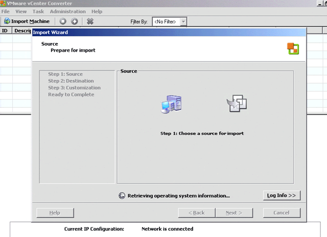
Now that I’ve shown all the options available under each tab, we proceed with clicking File –> New –> Import. This will start the vCenter Converter Import Wizard:

Proceed with clicking Next to allow vCenter Converter to detect the operating system of your physical host:


If you run into an error: Unable to determine Guest Operating System please click on below Link:
Click me

Once the operating system has been detected, you’ll see the following screen:

Typically don’t like to use the Import all disks and maintain size. option and prefer to use the Select volumes and resize to save or add space. option because you get more control over how the disks are virtualized. The options available will allow you to right-size the drives as you’ve planned during the planning phase:
I also find it important and consider it as best practice to check the Create a separate disk for each volume. option so that separate VMDKs are created for each disk. You’ll also sometimes find small partitions that are created by your server’s installation disks (usually recovery partitions) so uncheck those as you won’t need them once the virtual machine has been virtualized:


Once you’ve completed the configuration of the disks, continue on through the wizard:

Once you get to the following screen, choose the appropriate destination. Since we’re going to clone this physical server to the a vCenter server, choose the vSphere Virtual Machine option as the destination type:


The following screen will now allow you to enter the vCenter server address and credentials. I used to have problems back in the VI3 days where IPs didn’t appear to work but I have since tried both in vSphere and haven’t come across any problems so which one you use is up to you:

Once you’ve entered the credentials and click Next, the converter will reach out to your vCenter and validate the credentials:

If you’ve entered the incorrect credentials, you’ll see the following error message:
The system could not log you in. Please verify that the user name and password are correct, then try again. Passwords are case-sensitive.

Once the credentials have been validated, you’ll see the following screen where you can choose the virtual machine inventory location:


Proceeding to the next screen will give you the option of choosing which host, cluster or resource pool within a host or cluster you would like to place the virtual machine on:

The next screen will allow you to choose the specific host within the cluster you’ve chosen. This is important if you have servers that rely on other high availability options such as Windows NLB or MSCS where you would not want the active or passive node running on the same host:

Once you’ve selected the host you’d like the virtual machine to be hosted on, you’ll get to choose the datastore for the virtual machine:


The next screen will allow you to modify the NICs for the virtual machine. The wizard will always default to the amount of NICs that your physical server has so if you have more than you need, now is the time to change it. I also prefer to uncheck the Connect at powered on checkbox because I prefer to boot up the virtual machine after the p2v process has completed but it’s really just preference:

the next screen will give you the options:
Install VMware Tools
Customize the identity of the virtual machine
Remove all System Restore checkpoints
I usually prefer to select option #1 and # but not #2 because if I needed to change the virtual machine’s properties, I prefer to do it after it’s been virtualized.

The last screen will provide you with a summary of the virtual machine and what you’ve selected during the configuration as well as provide you with the option: Power on the new virtual machine after creation. While it’s not the default, I also select that option and this is why I prefer not to check the Connect at powered on checkbox:

Once you’ve completed the configuration through the import wizard, the task will start immediately as shown here:

How long the process will take always varies depending on how much data you need to virtualize and the network speed settings. Always remember to check what your physical server as well as your vCenter server network is connected at as there’s a significant difference between 100Mbps and 1Gbps.
As the process continues, you can monitor the progress in the Task Progress tab at the bottom of the window:

Once you’ve completed the cloning process, remember to perform cleanup tasks to remove any old vendor hardware specific devices hidden away in device manager. Also, newer versions of the converter typically fix the HAL for the process (Uniprocessor vs multiprocessor) but I always check the device manager to make sure it has been changed


Configuring HA on ESX hosts fails with the error: Cannot complete the configuration of the HA agent on the host (Re install HA agents)

Cannot configure HA on ESX hosts.
Unable to configure the aam agent.
Configuring HA on ESX hosts fails.
In vCenter Server one or more hosts in the HA cluster report the error:

Cannot complete the configuration of the HA agent on the host.

Resolution
This issue may occur if the vpxa agent on the ESX host is corrupted due to which you are unable to configure the aam agent.

Note: the below troubleshooting steps are not applicable to vCenter Server 5.0 as aam functionality is no longer used for HA on vCenter Server 5.0. For further HA (Fault Domain Manager) troubleshooting steps, see Troubleshooting Fault Domain Manager (FDM) problems (2004429).

To resolve this issue, remove the vpxa and aam agents from the ESX host and then reinstall them.

To remove the vpxa and aam agents:

Note: For information on reinstalling agents on an ESXi host, please reference KB 1027628
Connect to the ESX host using SSH.
Run this command to verify if the vpxa agent is installed:

# rpm -qa | grep vpxa

Note the vpxa package name returned by this command (For example, VMware-vpxa-#.#.#-#####).

Run this command to remove the vpxa agent:

# rpm -e <vpxa_package_name>

Where <vpxa_package_name> is the vpxa package name noted in Step 2.

For example:

# rpm -e VMware-vpxa-#.#.#-#####

Run this command to verify if the aam agent is installed:

# rpm -qa | grep aam

Note the two aam package names returned by this command. For example, VMware-aam-haa-#.#.#-# and VMware-aam-vcint-#.#.#-#.

Run this command to remove the aam package files:

rpm -e <aam_package_name>

Where <aam_package_name> is the aam package name noted in Step 4.

For example:

rpm -e VMware-aam-haa-#.#.#-#
rpm -e VMware-aam-vcint-#.#.#-#
To reinstall vpxa and aam agents:

Move the vpxa and aam agent installation files from vCenter Server to the ESX host using a secured file transfer utility, such as WinSCP.

Note: To download WinSCP, see http://winscp.net/.

To move files using WinSCP:
Open WinSCP and browse to C:\Program Files\VMware\Infrastructure\VirtualCenter Server\upgrade.
Upload these files to the /tmp directory of the ESX host (chose the highest available Build number):
vpx-upgrade-esx-7-linux-[BuildNumber]
aam-upgrade-esx-xxxxxxxx-[BuildNumber]prod-kcc-vip.vmware.com:8080/contactcenter/authoring/search.do?cmd=displayKC

Connect to the ESX host using SSH.
Browse to the /tmp directory.
Run these commands to install the agents:

# sh vpx-upgrade-esx-7-linux-[BuildNumber]
# sh aam-upgrade-esx-xxxxxxxx-[BuildNumber]

Run these commands to verify if the agents are installed:

# rpm -qa | grep vpxa
# rpm -qa | grep aam

Run these commands to restart services on the host:

# service mgmt-vmware restart
# service vmware-vpxa restart

Add the host back to vCenter Server.
Note: If the issue persists, disable and re-enable VMware High Availability in the cluster.